Installation
Instructions
SH-004 Photoelectric Smoke / Heat
Detector Kit
General
Information
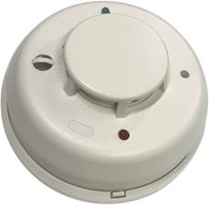
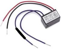
The SH-004 kit is designed for general use smoke detection and not for use in areas where steam and moisture could be abundantly present. For high moisture areas, the Maretron SH-005 kit is ideal. This kit contains a smoke detector and its mounting base and all original manufacturers installation and warranty information papers. Please retain the provided papers for additional reference such as maintenance frequency instructions. This kit also comes with an 8K Ohm EOL (End of Line) Resistor pre-installed to an EOL Relay necessary for circuit monitoring also known as 'circuit supervision'.
Installation Guidelines
·
Install SH-004 Kit in accordance
with ABYC and NFPA guidelines for fire and smoke detection based on your
application.
·
Never exceed 900 sq. ft. of area for any single
detector's range.
·
SH-004 Kit can be ceiling or wall mounted
directly or fastened to various sizes standard electrical boxes.
·
Pre-Mount and wire the SH-004 Kit base before
installing the head (detector unit).
·
The SH-004 base features a tamper lock. To
enable tamper lock (locking head), cut off plastic tab labeled 'Snip Off for
Tamper Lock'. Twist head (detector unit) onto base in a clockwise motion. To
remove, press release tab on base and twist head in a counterclockwise motion
·
Wire SH-004 Kit in accordance with ABYC or NEC
guidelines to select correct wire size (22-16 AWG) and any other applicable
wiring guidelines based on your application type.
·
The application of dielectric grease on the
detector base connections is recommended.
·
Do not mix high current harnessing with fire
detection harnessing. For best wiring choice, choose a marine grade, tinned copper,
16 AWG twisted pair cable.
· The SH-004 Kit comes with a pre-installed dust cover. Maintain cover affixed to detector throughout vessel construction or until first use.
Wiring &
Programming Instructions
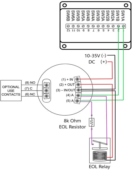
Please follow these instructions to connect the SH-004 to the NMEA 2000® network via a Maretron SIM100 Switch Indicator Module. The wiring diagram appears in Figure 1 on the reverse side of this page. The diagram shows a connection to channel #1 of the SIM100, but connections to other channels are similar.
1. Connect the SH-004 Kit power terminals (marked as (1) + IN and (3) – IN/OUT) to a 10 - 35 VDC supply that is independent of the NMEA 2000® network power supply as shown in Figure 1. Do not apply power until all connections are completed. Powering the unit separately from the NMEA 2000® network allows the detector to work even when the NMEA 2000® network is powered off.
2. Connect the power connection pig tail leads of the End Of Line Relay, Red (Positive Supply) to the alarm contact terminal (2) + OUT, Black (Negative Supply) to the alarm contact terminal (3) - IN/OUT as shown in Figure 1.
3. Connect the SH-004 two alarm contact terminals (marked (4) A and (5) A) to a free switch channel on the SIM100, followed by connecting the purple/violet pig tail leads of the End Of Line Relay to the same terminals. The example in Figure 1 shows the SH-004 smoke/heat detector connected to the SIM100 switch channel 1, terminals (marked SW1A and SW1B) and the relay connections to the End Of Line Relay.
4. Use a Maretron DSM Series display (firmware 1.3.5 or higher), or a Maretron USB100 and PC running N2KAnalyzer software to configure the SIM100 switch channel mode (indicated as “Channel #x Mode”) to the “End of Line Resistor” setting. For this example, you would set “Channel #1 Mode” to “End of Line Resistor”.
5. Supply Power to the NMEA 2000® network and to the SH-004 Kit, verify that the switch channel indicates an “off” (normal) state using a Maretron display, N2KAnalyzer, or a product capable of displaying switch indicator state.
6. Perform a smoke test and heat test on the SH-004 Kit and verify that the switch channel indicates an “on” (alarm) state during each of the tests.
7. Remove power from the SH-004 Kit and verify that the switch channel indicates an “error” state.
8. Reconnect power and verify that the switch channel indicates an “off” (normal) state.
9. Disconnect either of the two alarm wires from the SIM100, verify that the switch channel indicates an “error” state.
10. Reconnect the alarm wires to the SIM100 and verify that the switch channel indicates an “off” (normal) state.
|
|
WARNING: The SH-004 Kit is shipped with an 8KΩ resistor
installed in-line with the End of Line Relay contacts, covered with a heat shrink.
Do not remove the resistor as it is required for proper operation. NOTICE: The SH-004 Kit is packaged with the original
manufacturer’s Installation & Maintenance Instructions. Please retain these
documents and review for testing and maintenance procedures to be performed
on the smoke/heat detector and End of Line Relay. |

![]()
For installation support,
please contact:
Maretron
120 Intracoastal
Pointe Dr.
Jupiter, FL 33477
Telephone: (+1) 866-550-9100
E-mail:
[email protected]
Web: www.maretron.com